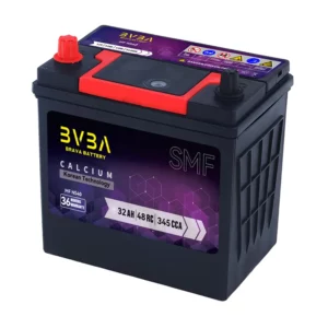
In this article, we are going to make a 6V lead-acid battery charger circuit in different ways. 6V lead-acid batteries were very common decades ago when portable emergency lanterns were very popular. But still, these batteries are being used in various devices. Sometimes, we need our custom battery charger circuit for this type of battery. So let’s find it out the ways we can make the battery chargers for these 6V lead-acid batteries.
Disclaimer: Electricity is always dangerous. Proper skill is required to work with electricity. Do work at your own risk. The author will not be responsible for any misuse or harmful act or any mistake you make. The contents of this website are unique and copyright protected. Kindly don’t do any nonsensical act copying and claiming it as yours. Most of the articles published here are kept as open-source to help you. Take the knowledge for free and use it, but if you are interested you can buy the ready resources offered here. If you need any help or guide feel free to comment below, the author will try to help you. Thanks.
Use of 6V lead-acid battery charger & Batteries:
The 6V lead-acid batteries were used in emergency portable lanterns in the early days. I had several of them in my childhood. But still, now these batteries are being used in different devices.
This one was very common at that time. The fluorescent tubes were used in this type of emergency light. As the storage, 6V lead-acid battery was used inside. Some of them had other facilities like a radio, fan, and torch.
Before starting the next please read this article: Get the long life of your Lead-Acid battery by selecting the right charging method
Note: Before you proceed note that this charger is not suitable for large batteries. It is only suitable for small batteries like <10Ah. Kindly do not use these small battery charger circuits for big batteries. Thanks.
Charging a 6V lead acid battery:
We are habituated to calculating the charging parameters of 12V batteries. Like that, we can keep the parameters similar for 6V batteries just changing the voltage limit by half. But before that, we must check this battery:
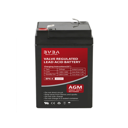
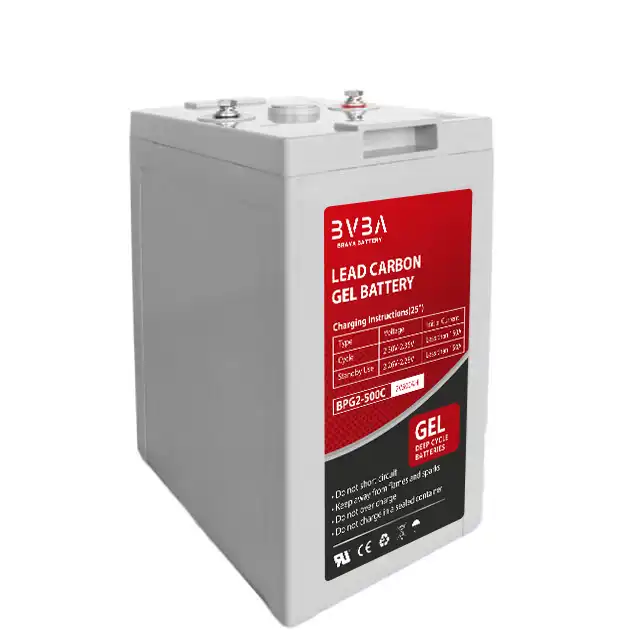
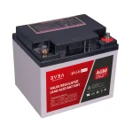
Can you see what the battery is telling you? If not, read this carefully:
It indicates 3 important values here. We must follow these 3 points when we charge the battery. Each battery can be used in 2 different modes.
- Standby mode
- Cycle mode.
Standby mode:
Standby mode is using the battery within a narrow voltage range either charging or discharging it. In online UPS or relevant devices, batteries are used in standby mode. In this mode, the battery is continuously charging, and at the same time, it is discharging. Just like a capacitor. Here this 6V battery indicates that in standby mode, the terminal voltage should be 6.75V to 6.9V. Otherwise, the battery may get heated and dried inside or even the battery plates may get damaged.
Cycle mode:
In cycle mode, the battery gets charge then it is disconnected from the charger. Afterward, the battery is only discharged (down to a certain level) when it is required. Once the battery is discharged, we need to charge that battery again to the full charge level. This is cycle use. Cycle use is common in those devices where there is no uninterrupted feature provided like UPS.
Voltage ranges:
When charging a battery, we must maintain two voltage ranges. One is the full cut (Full charge) voltage level and low cut ( Discharge) level. For a 6V Lead-Acid battery, these two voltages are 7.15V & 5.3V respectively. In some systems, the low limit is further lower(5.2V) than this. This is a very small variation but it’s important.
Charging methods:
For 6V batteries, we can follow two methods based on the use of the battery. Making a high configured charger sometimes may not be economical for these small batteries. And most of the systems use these two methods that we are going to see next.
- Standby charging
- 3 Step charging
So we can make our 6V lead-acid battery charger circuit in two modes. Let’s see.
Standby charging:
When you need the batteries not frequently but with a gap like several hours or days and no fast charging is required then this method is suitable for your battery. So what mechanism is kept here?
In this method, a simple voltage regulator circuit is used to supply a constant voltage. Check this circuit:
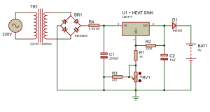
The circuit is very simple and easy to make. The 220V (or your line voltage range) is converted into 9V AC using a step-down transformer TR1. Then the AC supply is bridged with 4 1N5408 3A diodes and filtered by a capacitor (C1) 2200uF to make it pure DC. Afterward, a low valued series resistor R4 is used to limit inrush current which is important to protect both the regulator and transformer from burning. Then the legendary LM317T voltage regulator plays the final role here. But ensure that you used a sufficient heat sink with this voltage regulator as the regulator will be heating up a bit. R2, R1 is used to regulate the output voltage where R3||RV1 helps fine-tuning the output voltage. Then the power is delivered through the diode D1 (1N5408) to the battery.
Tuning:
First, disconnect the battery then measure the output voltage after the Diode D1. Tune the RV1 variable resistor and set the output voltage at 7.2V. Then connect the battery to the circuit.
Result:
This circuit will not cut the voltage when it reaches 7.2V but it will maintain that voltage until power cuts or the battery is discharged. The regulator LM317 is thermally protected so it will not be damaged for normal heat but a sufficient heat dissipation way with a heat sink (sometimes a colling fan can be used) is mandatory.
PCB design of the above circuit:
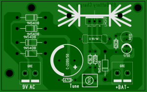
Pros & Cons of this circuit:
Pros:
- Circuit is very simple and low cost
- Easy to confirure
- Less failure
Cons:
- Current range 1.5A max
- Charging is never cut off rather than holding in standby position
- Battery may get heated if voltage selection is wrong
Current Extention:
To increase the current, the Diodes can be replaced by 10A10 and LM317 can be replaced by LM350. Besides changing the regulator IC, the series resistor R4 should be replaced by 2Watts and the heat sink must be increased in size. A cooling fan can be used too.
Full charge control interface:
Integrate the following changes to introduce full charge control with the above circuit.
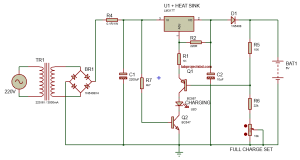
The Q1 is on when the battery is not fully charged. But once it is charged to a level, the Q1 is off which turns off the charging indicator LED. And the charging is activated only when the input is on through Q2. To set the full charge level, tune the FULL CHARGE SET variable keeping the battery disconnected. Once set, connect the battery to the terminal. When the battery is full, it automatically turns off the regulator and the CHARGING LED as well.
PCB for the modified circuit:
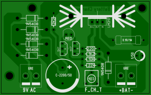
Why this circuit is used?
This circuit is small and suitable for most devices to maintain charging. Besides, only a few components are used makes it more economical. That is why this circuit is used in most systems. But some systems use SMPS battery charger circuits too.
About SMPS battery chargers:
Besides this linear system, SMPS or Switch Mode Power Supplies are also used for power conversion in some devices like the emergency lanterns of old times.
SMPS battery charger circuits are pretty complex compared to this linear one. If you don’t understand this linear one then it’s impossible to make something with SMPS one. That is why I’m not publishing SMPS circuits here in this post. Maybe in another article, I’ll write on this.
Notes:
With minor changes, you can use these circuits for 12V or even for 24V too if the required current is low.
3-Step charging:
The 3 Step charging is a little complex comparing to the linear one we discussed above but it is not too complex to make as well. In 3 step charging, the charging voltage and current are controlled in a certain way. After a full charge, trickle or float charging starts keeping the battery in healthy status. This circuit is suitable for large batteries but you can use it for 6V one too.
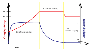
You are already known to this graph from the article: Get the long life of your Lead-Acid battery by selecting the right charging method.
Explanition:
At first, the battery is charged keeping a constant current (C/12, C = Ahr) rate until the battery rises to a certain voltage of 7.2V (for 6V). This first stage is the bulk charging state. Then in the topping charging state, the battery voltage is kept constant but the current reduces gradually. In this state, the battery gets the maximum pushing to store charge. When the current drops down to the C/200 level float state starts. In this floating state, the battery is not actually being charged but it maintains a level to keep the battery healthy. That’s it, Simple.
3 Step charging circuit selection:
You have seen that the method is a little automated and smart to select the operation modes. That is why we need special components to control everything. A small microcontroller can be used for this purpose. Besides, some dedicated battery charger ICs can be used.
The BQ24450 from Texas Instruments and some more from Analog Devices can help you in this case.
But these ICs are suitable for the production of battery charger circuits. For small quantities, using those ICs may not be economical at all. Now this situation can be overcome using a microcontroller. Let’s find it out.
Circuit diagram for 3-Step charging:
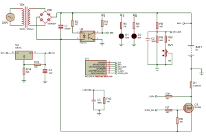
Here, we used PIC12F675 small microcontroller to do all the computing and processing works. From the left, the transformer is simply converting the AC220V into 9V as our previous circuits. Then the bridge & filter capacitor makes it DC. The Battery here is connected with this power source through a MOSFET rather than any regulator. Although we used a LM317L but not for charging purposes but regulating purposes to generate 3.3V to supply our microcontroller.
The Opto-Coupler here is sensing the presence of supply voltage and MCU is sensing it through its GP3 pin. RV1 is used to tune the battery voltage level. Once the circuit is powered up, turn on the supply and slowly tune the RV1 to set the first high cut (Full Charge Voltage) point. Then it will work normally. LED D1 (CHR) indicates the charging mode. Fast blink for Bulk charging mode, Slow for Topping, and Off for float mode. The battery indicator LED D2 (BAT) is on when the battery is fully charged and kept in maintenance mode.
The Circuit uses a shunt resistor R1 (0.22Ω/2W) to sense the current.
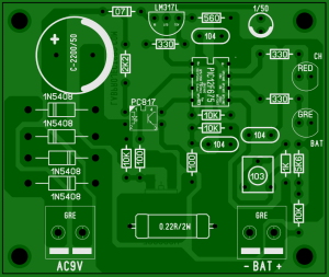
PCB for the above circuit:
Before starting the programming of our circuit, I recommend you to read this article first: PWM pulse generation using PIC12F675 micro-controller
Programming:
The code is written in mikroC pro for PIC v7.6.0. The interrupt used here is a timer interrupt to generate the PWM signal that I already described in my article: PWM pulse generation using PIC12F675 micro-controller. The rest of the programming is simply doing the battery charging in 3 steps.
Basic explanation:
The part of the code:
We are sensing the battery from here. You may ask where I got the 0.086? Simple. Here, we are using 3V3 as our VDD. Also, this is our ADC reference value. That is why with the 10bit ADC and the resistor voltage divider with 10K & (6.8K||(1K+VR)) gives us (3.3/1023) * ((10K+6.0K)/6.0K). Now, we are not taking the floating-point data here. That is why to measure the fractional voltage of the battery, we simply multiplied that value by 10. That means, if the ADC pin senses the battery voltage as 6.5V, we can not get the .5V fraction if we don’t multiply it by 10. But we can get 65 if we do that.
Similarly, for current sensing, we got our values which are//-ed in the code.
And in this block, we are simply making a 3 step charging. Although we did not make so many complex calculations or loops, it is fine for a 6V battery.
Here, if your battery is large and expensive, you must use a larger microcontroller to do more loops that will make the system safe. If you need help for that purpose don’t wait to contact us.
Pros and Cons:
Like the previous analog circuit, this one has some good and bad sides as well.
Pros:
- High efficient
- Proper charging
- Battery management
- Battery long life
Cons:
- Complex & need experience to make
- Little expensive
Why this type of circuit is used?
If the circuit is complex and expensive then why this type of circuit is used? Yes, when the battery needs lots of attention and you need to run the battery for a long time then it is really required to use such a complex circuit. Even here I designed a simple one for you so that you can understand. But in real life, this circuit may have other features and faster speed.
Tag in this article: #Battery
Tips: more detail information, for acid battery。


