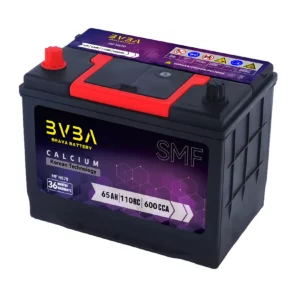
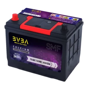
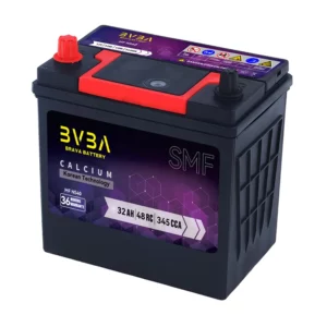
Lifepo4 battery BMS SP04S034
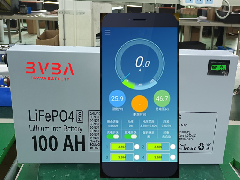
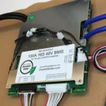
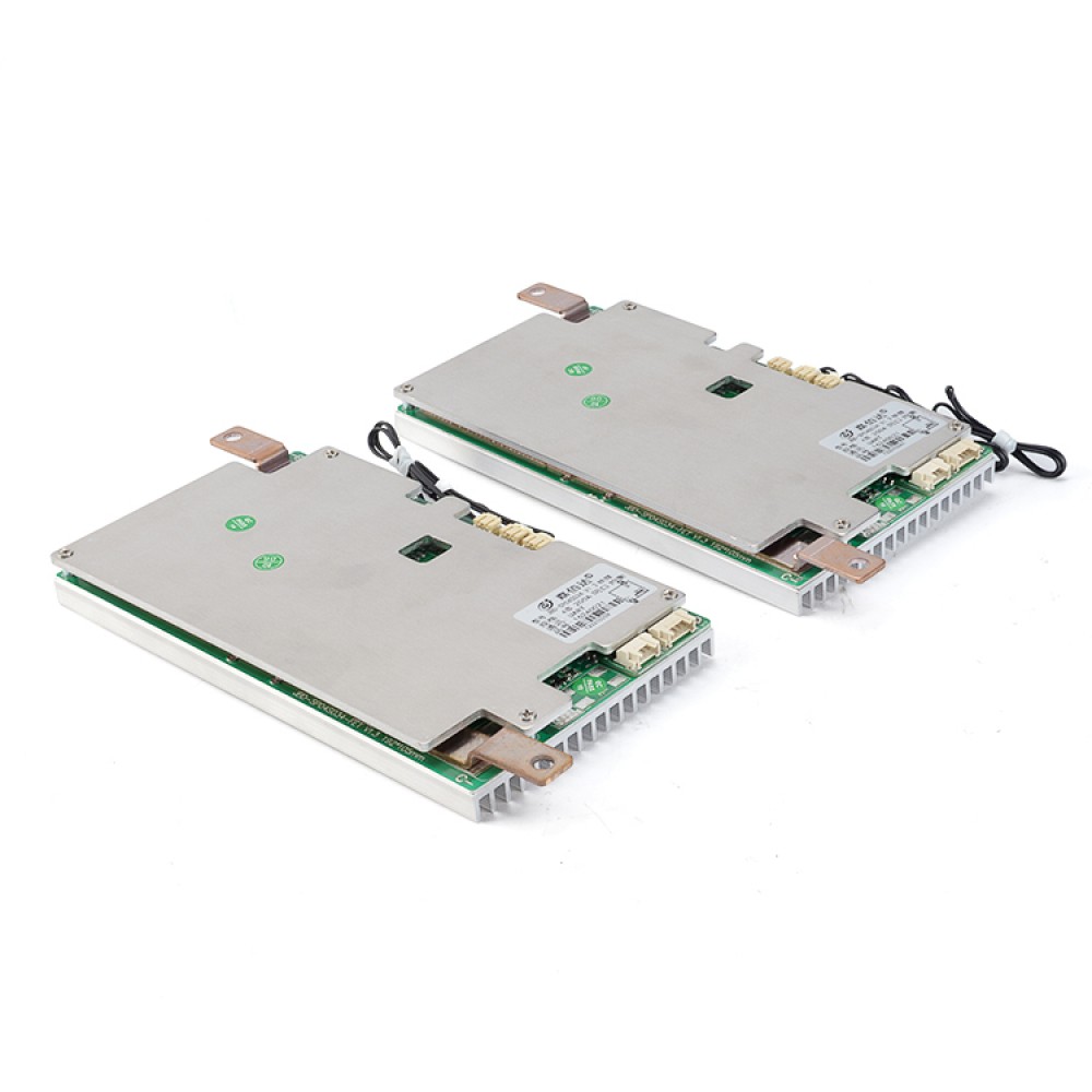
JBD-SP04S034 is an intelligent protection board designed by Dongguan Jiabaida Electronic Technology Co., Ltd. specifically for starting lifepo4 battery, energy storage and other products 4 series battery packs;Suitable for different chemical properties of lithium cells, such as lithium ion, lithium polymer, lithium iron phosphate, etc.Protection plate with strong load capacity, continuous discharge current up to 200A.
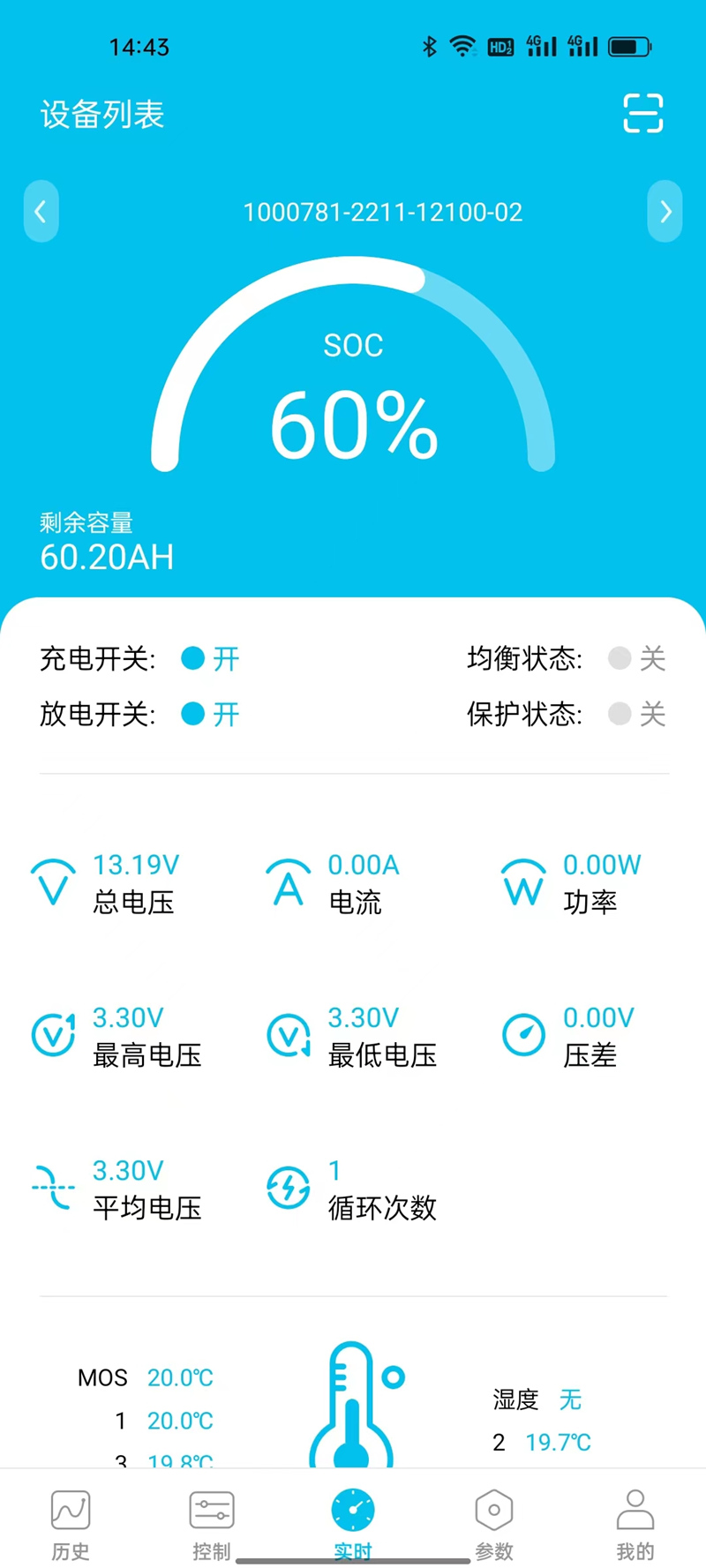
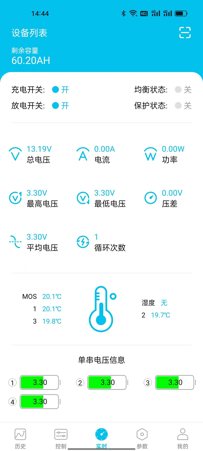
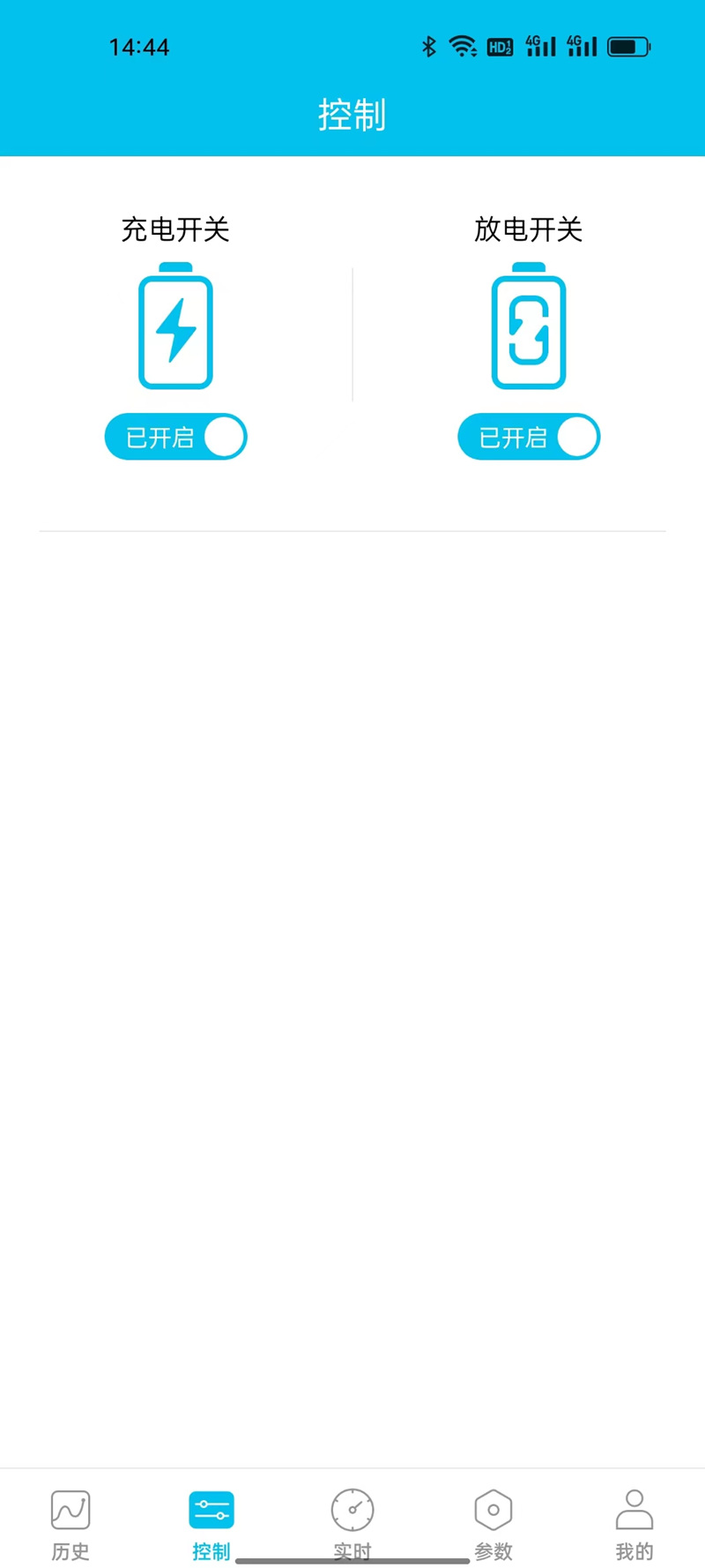
- 4 cell series protection
- Various protection functions for charging and discharging
- Discharge over current, short circuit protection functional processes of hardware
- Over voltage, under voltage, temperature and overload protection function processing of software
- Accurate SOC calculation with automatic SOC learning function
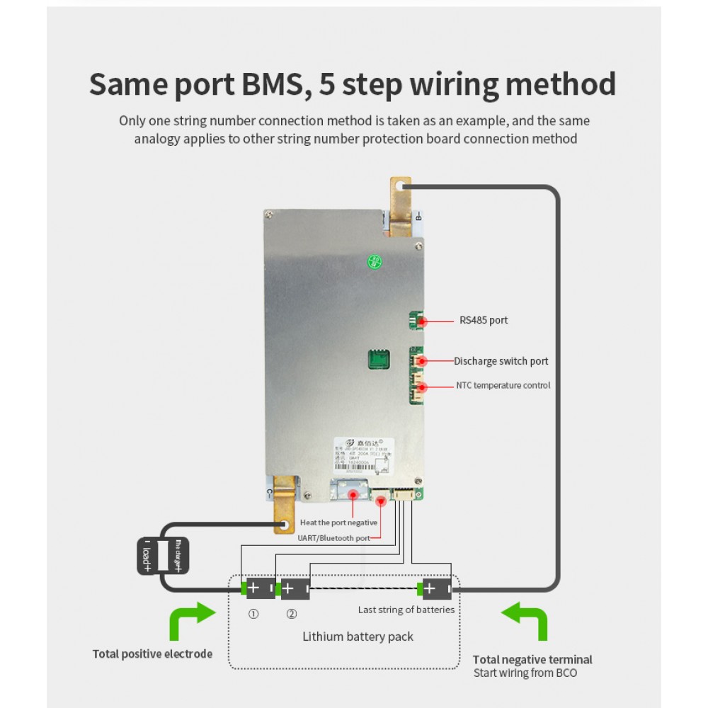
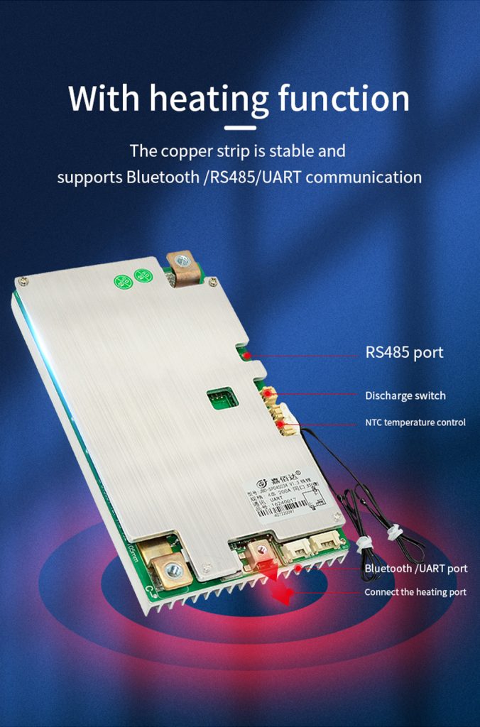
- UART/RS485 communication function, can read all data of battery in real time and upgrade online
- Hardware discharge over-current, short-circuit protection function processing
- Reserved switch control protection panel output and low temperature charging and heating function
BMS Quick Details
Model Number: SP04S034
Type: bms pcba
Place of Origin: China
Brand Name: JBD
Product Name: lifepo4 bms
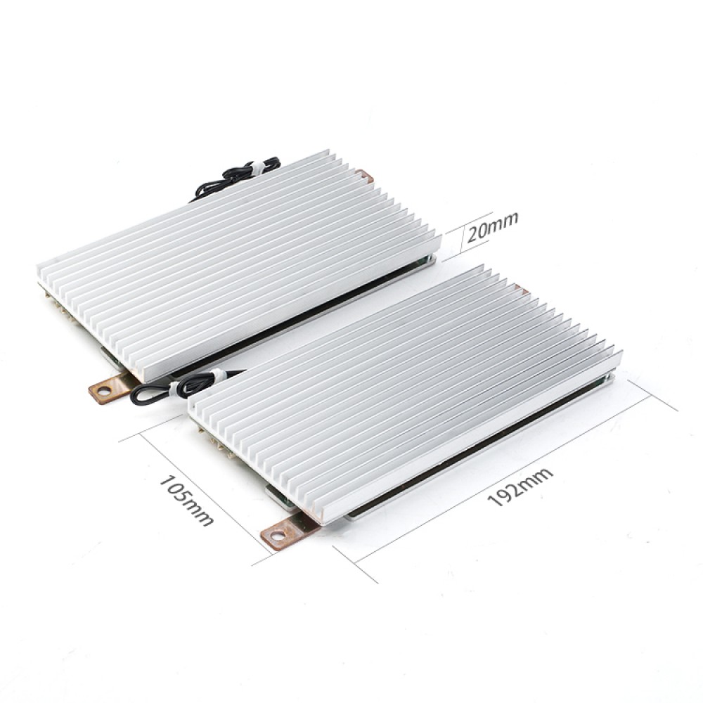
Product Size: 232*105*20mm
Customized: Yes
Communication Protocol: Bluetooth/RS485/UART/Heating
String: 3-4S
Sample Time: 1-3 Working day
Testing Service: 100% Testing
Usage: Lithium Battery Pack
Short-circuit protection: yes
Charge/discharge protection: yes
BMS Packaging & Delivery
Selling Units: Single item
Single package size: 23X13X16 cm
Single gross weight: 1.000 kg
Package Type: Manufactuers will upgrade the packaging sometimes,please refer to the actual object received.
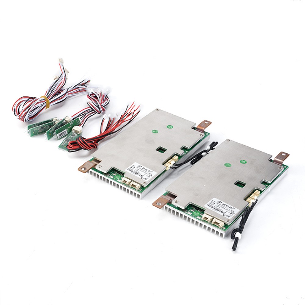
Package Content : 1* BMS *Balance wires* Bluetooth Module
Note: UART/RS485 communication box should be purchased seperately
BMS Lifepo4 battery Details :
| Operating Current (MAX) | 150A |
| Connection Port | same port for charge and discharge |
| Charge voltage(recommend) | 14.4V |
| Working voltage range | 9.2v-15.0v |
| Short Circuit Protection | Yes |
| Internal Resistance | <10mR |
| Working Temperature | -30 degree~75 degree |
| Discharge Protection overtemperature | 72~78 degree |
| Charge Protection overcurrent | 160~200A |
| Discharge protection undertemperature | -25-15 degree |
Lifepo4 battery BMS Protection function description
Overcharge protection: When the battery is under the charging state, the voltage keeps going up. When the protection board detects that the voltage of any cell is higher than the overcharge protection value, the protection board will start timing immediately. When the time reaches the overcharge protection delay, the protection board will turn off the charging MOS tube, at that time, it cannot be charged.
Overcharge protection recovery: After the overvoltage protection appears on the protection board, the battery voltage will going down under the static or discharge state of the battery. When the protection board detects that each voltage is lower than the recovery voltage of the overcharge protection, the protection board will output a signal and turn on the charging MOS tube to charge.
Over-discharge protection: When the battery is under the discharge state, the voltage keeps going down. When the protection board detects that the voltage of any cell is lower than the overcharge protection value, the protection board will start timing immediately. When the time reaches the over discharge protection delay, the output signal of the protection board will turn off the discharge MOS tube, the load lock circuit will work, but, it cannot discharge at this time.
Over discharge protection recovery: After the over discharge protection appears on the protection board, the battery voltage will going up under the static or discharge state of the battery. When the protection board detects that each voltage is higher than the recovery voltage of the over discharge protection. At this time, disconnect the load or charge, the protection board will output a signal and turn on the charging MOS tube to charge.
Overcurrent protection: When the battery is under the static or discharge state, the current suddenly increases. When the protection board detects that the current reaches the overcurrent protection value, the protection board will start timing at that time. When the current duration in the circuit reaches the overcurrent protection delay time, the output signal of the protection board will turn off the discharge MOS tube, and the load lock circuit will work. At this time, the discharge cannot be conducted.
Overcurrent protection recovery: After the discharge overcurrent protection appears on the protection board, the discharge MOS tube is turned off, and the current in the loop becomes 0. At this time, the load is disconnected or charged, the output signal of the protection board will turn on the discharge MOS tube to discharge.
Over-charging Protection and recovery
Cell overcharge protection and recovery When the voltage of any cell is higher than the set
value of cell overcharge voltage, and the duration reaches the cell overcharge delay, the system
enters the overcharge protection state, and the charging MOS is turned off , Cannot charge the
battery. After the cell overcharge protection, when the voltage of all cells drops below the cell
overcharge recovery value, the overcharge protection state is released. It can also be discharged.
Overall overcharge protection and recovery When the overall voltage is higher than the
overall overvoltage set value, and the duration reaches the overall overcharge delay, the system
enters the overcharge protection state, the charging MOS is turned off, and the battery cannot be
charged. When the overall voltage drops below the overall voltage overvoltage protection
recovery value, the overcharge protection state is released, and the discharge can also be
released.
Overdischarge protection and recovery
Cell overdischarge protection and recovery
When the lowest cell voltage is lower than the cell overdischarge voltage setting value,
and the duration reaches the cell overdischarge delay, the system enters Over-discharge
protection status, turn off the discharge MOS, and cannot discharge the battery
After the monomer over-discharge protection occurs, charging the battery pack can release the
over-discharge protection state.
Overall over-discharge protection and recovery
When the overall voltage is lower than the overall over-discharge voltage setting value, and the
duration reaches the overall over-discharge delay, the system enters the over-discharge
protection state, the discharge MOS is turned off, and the battery cannot be discharged
Charging overcurrent protection and recovery When the charging current exceeds the
charging overcurrent protection current and the duration reaches the overcurrent detection delay
time, the system enters the charging overcurrent protection state and the battery cannot be
charged. After the charging overcurrent protection occurs, the delay will automatically recover. If
you don’t need to automatically recover, you can set the corresponding release time longer;
discharge can also release the charging overcurrent state.
Discharge overcurrent protection and recovery When the discharge current exceeds the
discharge overcurrent protection current and the duration reaches the overcurrent detection delay
time, the system enters the charge overcurrent protection state, and the discharge MOS is turned
off. After the discharge overcurrent occurs, the delay will automatically recover. If the automatic
recovery is not required, the corresponding release time can be set to be longer. Charging can
also release the discharge overcurrent state. The discharge has two-level over-current protection
functions, which have different response speeds to different current values, and protect the
battery more reliably.
The temperature protection and recovery management system has two temperature
detection ports, which can be used for temperature protection with NTC.
Charge and discharge high temperature protection and recovery. When the NTC detects
that the temperature of the cell surface is higher than the set high temperature protection
temperature during charging and discharging, the management system enters the high
temperature protection state, and the charging or discharging MOSFET is turned off. The battery
cannot be protected in this state. Pack charging or discharging. When the temperature of the
battery cell surface drops to the high temperature recovery set value, the management system
recovers from the high temperature state and reconnects the charge and discharge MOS.
Charge and discharge low-temperature protection and recovery. When the NTC detects
that the temperature of the cell surface is lower than the set low-temperature protection
temperature during charging and discharging, the management system enters the
low-temperature protection state, and the charging or discharging MOSFET is turned off. Pack
charging or discharging. When the temperature of the battery cell surface rises to the low
temperature recovery setting value, the management system recovers from the low temperature
state and reconnects the charge and discharge MOS.
In static state (without charging and discharging), if the temperature rises or drops to the
protection board, the protection board will not make any protection action until the system detects
a current, then the corresponding protection action will be made.
1. What type of charger should I choose?
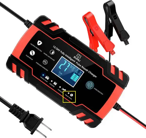
BravaBattery Lithium battery must choose specific charger, do not use Charger for Leadacid battery, for leadacid charger may have MOS with high pressure breakdown protection, which will not protect of BMS over charge. Life Po4 battery charger voltage=battery string No.X3.6V, while Li-ion battery charger voltage=Battery string No.X4.2V.
2.The relationship between Battery capacity and BMS current?
There is no direct relationship between Battery capacity and BMS current, big capacity doesn`t mean a big battery, but rely on continue current, that is to say if your engine is powerful, your should choose high current of BMS, it is not relied on battery capacity.
3.Whether my BMS damaged?
If you want to judge if the BMS is damaged, please take the folowing steps, to test if each cell voltage is the same with
voltmeter? if the cell voltage difference is over 1.0V, the fault is displayed that it cannot run far, no power supply at the
start range, short charge time, all these issues are almost caused by battery cells, if BMS damaged is displyed as no charge, no discharge, no discharge while the battery has voltage.
LifePO4 Batteries Related Products:
Related Products Application:
LifePO4 Batteries Related Posts:
Tag in this article: #LiFePO4 Battery
Tips: more detail information, for deep cycle LiFePO4 battery。

