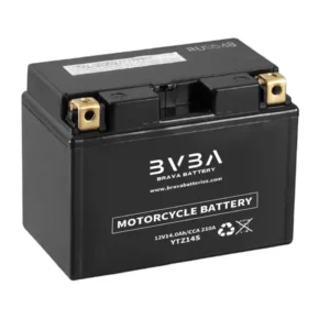
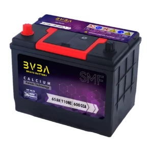
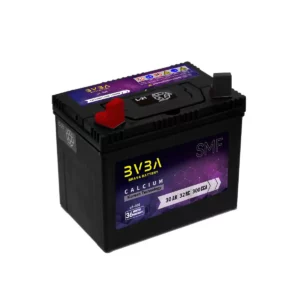
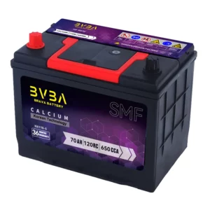
The BMS Module support Lifepo4 Battery 16 cells serial upto 150A.
BMS Shield
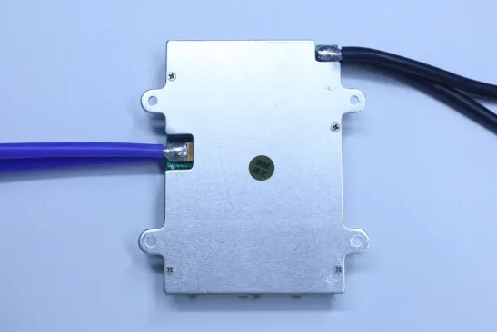
BMS 16s80A with shield
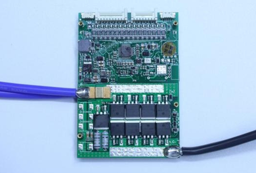
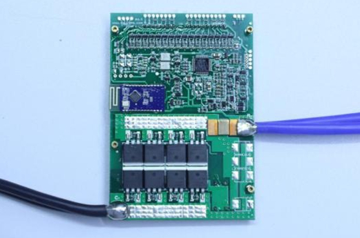
BMS PCBA
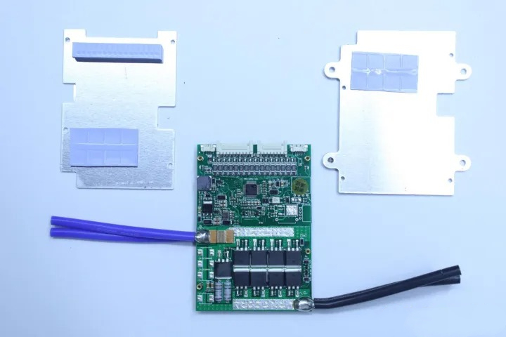
front side of BMS PCBA
Back side of BMS PCBA
MCU
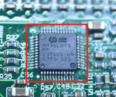
Ultra-low-power 32-bit MCU Arm®-based Cortex®-M0+, up to 192KB Flash, 20KB SRAM, 6KB EEPROM, LCD, USB, ADC, DACs
Features
Includes ST state-of-the-art patented technology
• Ultra-low-power platform
– 1.65 V to 3.6 V power supply
– -40 to 125 °C temperature range
– 0.29 µA Standby mode (3 wakeup pins)
– 0.43 µA Stop mode (16 wakeup lines)
– 0.86 µA Stop mode + RTC + 20-Kbyte RAM retention
– Down to 93 µA/MHz in Run mode
– 5 µs wakeup time (from Flash memory)
– 41 µA 12-bit ADC conversion at 10 ksps
• Core: Arm® 32-bit Cortex®-M0+ with MPU
– From 32 kHz up to 32 MHz max.
– 0.95 DMIPS/MHz
• Memories
– Up to 192-Kbyte Flash memory with ECC
(2 banks with read-while-write capability)
– 20-Kbyte RAM
– 6 Kbytes of data EEPROM with ECC
– 20-byte backup register
– Sector protection against R/W operation
• Up to 84 fast I/Os (78 I/Os 5V tolerant)
• Reset and supply management
– Ultra-safe, low-power BOR (brownout
reset) with 5 selectable thresholds
– Ultra-low-power POR/PDR
– Programmable voltage detector (PVD)
• Clock sources
– 1 to 25 MHz crystal oscillator
– 32 kHz oscillator for RTC with calibration
– High speed internal 16 MHz factorytrimmed RC (+/- 1%)
– Internal low-power 37 kHz RC
– Internal multispeed low-power 65 kHz to
4.2 MHz RC
– Internal self calibration of 48 MHz RC for
USB
– PLL for CPU clock
• Pre-programmed bootloader
– USB, USART supported
• Development support
– Serial wire debug supported
• LCD driver for up to 4×52 or 8×48 segments
– Support contrast adjustment
– Support blinking mode
– Step-up converted on board
• Rich Analog peripherals
– 12-bit ADC 1.14 Msps up to 16 channels (down to 1.65 V)
– 2 x 12-bit channel DACs with output buffers (down to 1.8 V)
– 2x ultra-low-power comparators (window mode and wake up capability, down to
1.65 V)
• Up to 24 capacitive sensing channels supporting touchkey, linear and rotary touch sensors
• 7-channel DMA controller, supporting ADC, SPI, I2C, USART, DAC, Timers
• 11x peripheral communication interfaces
– 1x USB 2.0 crystal-less, battery charging detection and LPM
– 4x USART (2 with ISO 7816, IrDA), 1x
UART (low power)
– Up to 6x SPI 16 Mbits/s
– 3x I2C (2 with SMBus/PMBus)
• 11x timers: 2x 16-bit with up to 4 channels, 2x
16-bit with up to 2 channels, 1x 16-bit ultra-lowpower timer, 1x SysTick, 1x RTC, 2x 16-bit
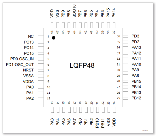
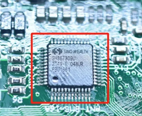
DSP SH367309
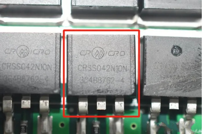
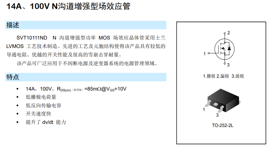
Mosfet CRSS042N10N
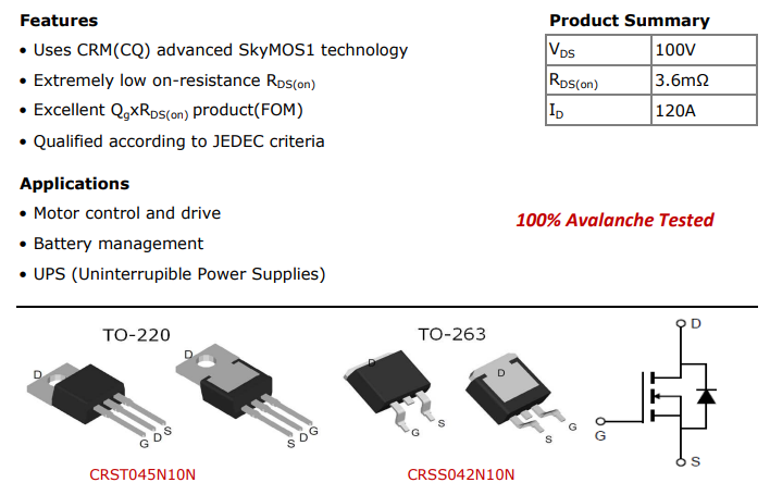
Features
• Uses CRM(CQ) advanced SkyMOS1 technology
• Extremely low on-resistance RDS(on)
• Excellent QgxRDS(on) product(FOM)
• Qualified according to JEDEC criteria
Applications
• Motor control and drive
• Battery management
• UPS (Uninterrupible Power Supplies)
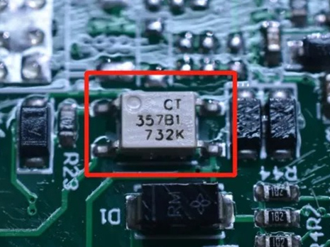
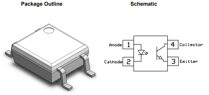
DC Input 4-Pin Mini-Flat Phototransistor Optocoupler
Features
High isolation 3750 VRMS
Multiple CTR selection available
DC input with transistor output
Creepage distance ≥5mm
Operating temperature range – 55 °C to 110 °C
Green Package
Regulatory Approvals
UL – UL1577 (E364000)
VDE – EN60747-5-5(VDE0884-5)
CQC – GB4943.1, GB8898
IEC60065, IEC60950
Description
These series of general purpose optocoupler
consists of a photo transistor optically coupled to a
gallium arsenide Infrared-emitting diode in a 4-lead Mini-Flat package.
Applications
DC-DC Converters
Programmable controllers
Telecommunication equipment
Hybrid substrates that require high density mounting
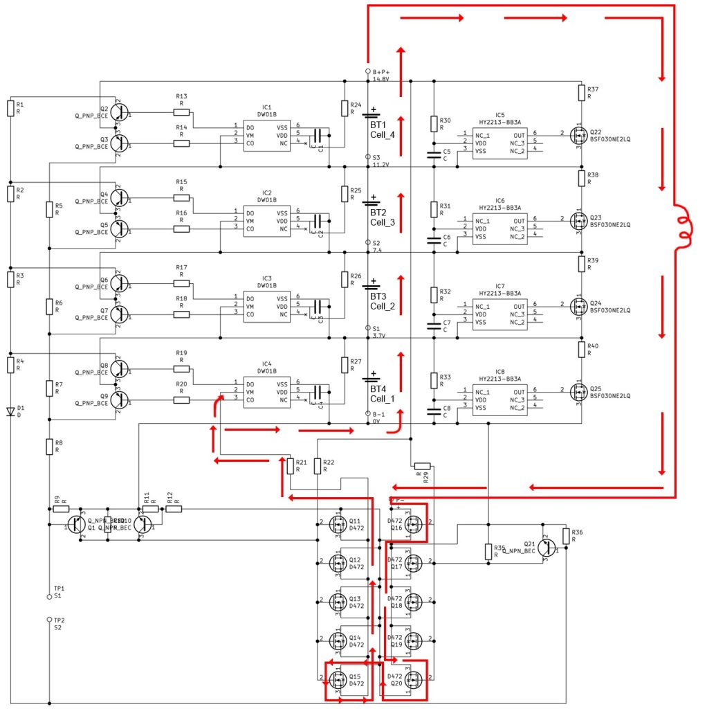
Schematic Diagram
LifePO4 Batteries Related Products:
Related Products Application:
LifePO4 Batteries Related Posts:
Tags: BMS. LiFePO4 battery.

